Product Center
———

Electrical Test Equipment · Voltage Conversion Device
Voltage Conversion Device
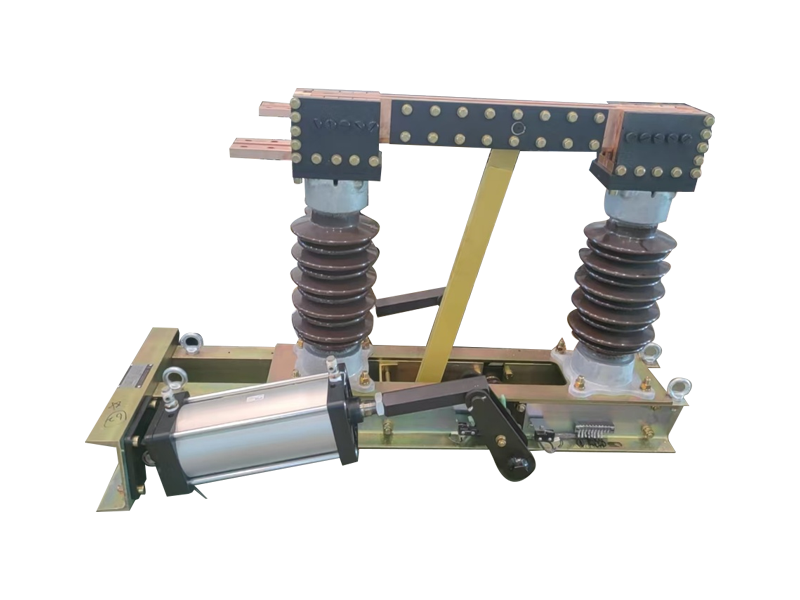
AT series voltage conversion device is a three-phase medium-voltage conversion and circuit switching equipment for power equipment test systems. It consists of insulator-supported busbars, multi-position changeover switches, optional current-limiting reactors and a steel frame. It realizes flexible conversion and isolation between 6kV/10kV/35kV test power supplies, DUTs and load circuits, often combined with LV/DC impedance, capacitive/active loads and adjustable reactors to build complete test load circuits.
Application
AT series voltage conversion device is the core conversion equipment in power equipment test stations, used to convert test power supplies to different voltage levels or distribute power to different test circuits. Main applications include:
MV-side circuit conversion for transformer short-circuit, temperature rise and load loss tests
Power connection and conversion for MV switchgear and circuit breaker dynamic/thermal stability tests
MV test wiring conversion for generators, motors, variable frequency drives and UPS
Combined switching and voltage matching of capacitor banks, reactors and resistive loads
Unified conversion hub for multi-voltage-level (6kV/10kV/35kV) test platforms
Power distribution, isolation and protection between different test stations
Structural Features
Three-phase independent structure: Left, center and right columns, each phase conductive circuit independently insulated with sufficient phase-to-phase clearance
Insulator support: HV conductive busbars supported by porcelain or composite insulators, meeting MV insulation requirements
Multi-position changeover switch: Each phase equipped with multi-position knife switch or changeover switch for safe switching between different voltage levels/circuits
Three-phase color-coded busbars: Red, yellow and green phase colors for easy on-site identification and wiring
Optional current-limiting reactor: Internal air-core or iron-core reactor can be integrated to limit inrush current during short-circuit tests
Steel frame base: Welded frame structure, stable, easy for lifting, transport and installation
Mechanical/electrical interlock: Interlocks at critical switching positions to prevent on-load misoperation
Visible breaking gap: Switch breaking gap visible for confirming isolation status and ensuring test safety
Selection Guide
10kV transformer test station: Choose 12kV rated voltage, 1000A-3000A rated current, 31.5kA short-time withstand
35kV transformer test station: Choose 40.5kV rated voltage, 2000A-5000A rated current, 50kA-80kA short-time withstand
High-capacity short-circuit test: Optional current-limiting reactor (4%-8% reactance) to reduce impact on upstream power supply
Multi-voltage compatibility: Choose 3-4 position changeover switch to cover 6kV/10kV/35kV
Frequent operation: Choose electric operating mechanism with remote control interface
Outdoor test station: Choose IP54 protection, anti-pollution flashover insulators
Related Products
Voltage Conversion Panel
View Details →